Advanced Ceramic 3D Printing

Explore Our 3D Printing Service for Custom Advanced Ceramic Components

Our Process of Additive Manufacturing of Advanced Ceramics

Our advanced ceramic 3D printing service leverages stereolithography-based technology from Admatec, enabling precise, efficient, and cost-effective production of complex ceramic geometries. Use our instant pricing tool to upload your CAD model and receive an immediate quotation.

From Ceramic Slurry to Dense Ceramic Parts

The process begins with a slurry composed of a photosensitive resin mixed with high-purity ceramic powder. Using Digital Light Processing (DLP), a specialized form of UV-light exposure, the ceramic particles are selectively cured layer-by-layer, forming a so-called “green body.” At this stage, the part consists of ceramic particles embedded in a polymer matrix.

This composite structure undergoes controlled thermal treatments: initially, polymer removal through debinding, followed by high-temperature sintering at temperatures above 2912°F (1600°C). Only after these steps does the part reach its final properties – fully dense advanced ceramic with excellent mechanical strength and chemical resistance.

Advantages of 3D Printing of Ceramics

Unmatched Design Freedom and Complex Geometries

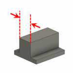
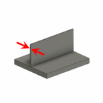
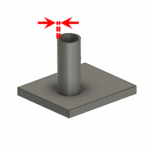
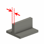
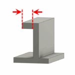
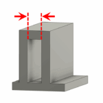
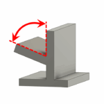
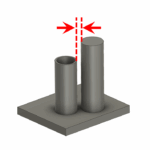
Our ceramic 3D printing enables fabrication of intricate geometries and fine structures unattainable through traditional manufacturing methods such as milling, grinding, pressing, or injection molding. Complex, lightweight geometries like bone-like scaffolds, thin-walled crucibles with wall thicknesses down to 0.3 mm, and intricate internal channels or nozzles become easily achievable.
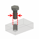
 Threads as small as M2 can be printed directly; however, for threads requiring higher precision and mechanical load capacity, we recommend our subsequent CNC grinding.

High-Purity and Customizable Ceramic Materials

Our standard slurry formulations include high-purity 99.9% Al₂O₃ and 3mol% Yttria-stabilized ZrO₂ (YSZ). Additionally, we provide tailored blends such as Zirconia-Toughened Alumina ATZ with standard formulations of ZTA-5%-ZrO₂ and ZTA-15%-ZrO₂, enabling customized solutions for specific application requirements.

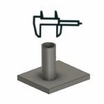
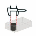
Precision and Accuracy

Our DLP technology achieves a native pixel resolution of 50 µm, resulting in dimensional tolerances of ±1.5% (minimum ±0.15 mm). Accuracy limitations mainly arise from shrinkage-induced distortion during sintering. For applications demanding even greater precision, our CNC grinding is available, capable of achieving tolerances up to ±5 µm on selected features.

Fully Dense, Gas-Tight Components

Despite a linear shrinkage of approximately 30% during sintering, our 3D-printed ceramic parts achieve densities up to 99.4% of theoretical density, making them fully dense, gas-tight, and suitable for demanding industrial applications.

Comparable Mechanical Strength to Machined Ceramics

The mechanical strength of our 3D-printed ceramics approaches that of conventionally machined ceramics. Ceramic strength is inherently statistical, influenced by microstructural defects. Although the layer-by-layer printing process has a slightly higher probability of microstructural irregularities compared to fully pressed and machined ceramics, the resultant strength difference is minimal for most applications. If your application involves significant mechanical loading, we recommend consulting with our engineering team. We can suggest alternative solutions such as using tougher ceramics like ZrO₂ or redesigning parts to minimize tensile stresses – ceramics typically withstand compressive stresses up to 10 times better than tensile loads.

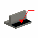
Excellent Surface Quality

Our additive manufacturing process produces surfaces with roughness typically between Ra 0.6 – 1.2 µm, depending on orientation during printing. For applications demanding superior surface finishes, we offer CNC grinding and polishing services, achieving mirror-polished surfaces down to Ra = 0.01 µm.

Economically Viable for Small Complex Parts

While ceramic 3D printing scales with the cubic dimensions of the parts—meaning larger components become disproportionately costly—it offers unmatched economic efficiency for small, intricate parts. For small-sized geometries, our additive manufacturing service can even outperform ceramic injection molding in terms of cost-per-part. Use our convenient online pricing tool to quickly determine if ceramic 3D printing is the optimal solution for your project.

Table of Requirements for 3D Printing of Ceramics

VisualProperty / RequirementValue
3D schematic showing maximum printable part dimensions in X, Y, and Z directions for ceramic 3D printingBounding Box (max. part size)X: 74 mm / Y: 41 mm / Z: 80 mm
Semi-transparent rectangular part with a curved internal channel; red arrows indicate the smallest printable channel diameterSmallest printable channel1 mm
Cross-section of a semi-transparent printed part showing a short, straight hole with red arrows indicating the minimum printable diameter in thin wall sectionsSmallest printable hole in thin wall sections0.1 mm
3D-printed part with two red arrows indicating the maximum printable wall thickness in ceramicsMaximum wall thickness10 mm
Thin vertical wall printed without support, highlighted by red arrows to indicate the minimum printable free-standing wall thickness in ceramicsMinimum wall thickness (free)0.5 mm
Cylindrical wall printed vertically with red arrows indicating the minimum self-supported wall thickness in ceramic 3D printingMinimum wall thickness (self-supported, e.g. cylindrical tube)0.3 mm
Wall thickness highlighted by red dashed arrows, illustrating the optimal range for 3D-printed ceramic partsOptimal wall thickness1–3 mm
Horizontal surface with no support underneath, highlighted by red dashed arrows to show the maximum printable free overhang lengthFree overhang (without support structure)up to 2 mm
Double-sided unsupported overhang in a 3D-printed part, with red dashed arrows indicating a maximum printable span without supportFree overhang on both sides (without support structure)up to 3 mm
Unsupported overhang surface with red dashed lines and arrows illustrating the maximum printable free overhang angleMaximum free overhang angle (without support structure)70°
Two vertical printed features with red dashed arrows indicating the minimum required spacing between adjacent structures in ceramic 3D printingMinimum distance between features2 mm
illustration of Caliper and 3d printed cylindrical part, symbolizing general dimensional tolerances of 3d printed ceramic partGeneral tolerance±1.5 % (minimum ±0.15 mm)
Caliper measuring the diameter of a printed hole, representing achievable dimensional tolerance of bores in advanced ceramicsTolerance for bores±0.050 mm
Threaded bolt aligned with a printed internal thread inside a transparent part; red dashed arrows indicate the minimum printable thread size Smallest printable threadM2 or larger, ground thread recom.
Arrow pointing to horizontal printed surface to indicate in-layer surface roughness of ceramic partIn-layer roughnessRa 0.4
Arrow pointing to vertical surface of a 3d printed part to indicate layer-to-layer surface roughness due to build directionLayer-to-layer roughnessRa 1.5
Magnified view of voxel dimensions represented by red arrows inside a dashed box, illustrating the final 3d printed resolution after sinteringVoxel size after sintering38 µm