Engineering for Advanced Ceramics
Designing with advanced ceramics requires more than material knowledge — it requires deep process understanding, close collaboration, and engineering experience. We support our clients from the first sketch to fully optimized, cost-effective designs for ceramic manufacturing.

>> Partner With Our Experts To Engineer Your Parts Right The First Time<<
Why Designing for Ceramics Is Different?
Ceramics shrink during sintering — up to 30%. That shrinkage isn’t always linear; it depends on geometry, wall thickness, and how the part is supported during firing. Thin walls often shrink faster, and asymmetry can lead to distortion.
Customers often approach us with a part originally designed for metal. Simply keeping that design will usually not work. There are three key guidelines that must be considered:
1. Engineering for the Application

What property does the application require?
The most critical functional demands of your application determine which ceramic material (or combination) we’ll use.

Tolerances
The required dimensional tolerances define the shaping method. If tolerances below 0.1 mm are needed, hard grinding is the only viable solution.
Projected quantity
Your expected production volume influences the manufacturing approach. 3D printing is ideal for prototypes and small batches, while increasing quantities make milling more economical.
2. Engineering for Ceramics

Avoid sharp, protruding features
In green machining, thin or unsupported structures are fragile and prone to breaking. During sintering, such features are likely to deform due to low rigidity. The only process that allows protrusions to some extent is hard grinding

Avoid thin and inhomogeneous wall thicknesses
Thin walls tend to shrink faster during sintering, leading to distortion. Maintain uniform wall thicknesses where possible, especially where walls meet.
If a transition between thin and thick sections is unavoidable due to design constraints, apply generous radii to soften the cross-sectional change and reduce stress concentration during sintering.

Minimize tensile stress
Ceramics can handle compressive stress up to 10 times better than tensile stress. Good design turns tension into compression wherever possible to increase durability.

Use symmetry
Symmetrical parts distribute sintering stresses evenly and help prevent warping or distortion.

Avoid extreme aspect ratios
Large differences in dimensions (e.g., length vs. width) reduce structural stability during sintering and promote deflection.
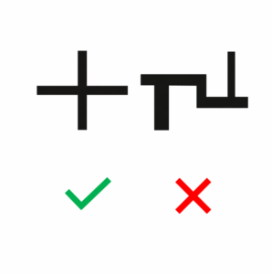
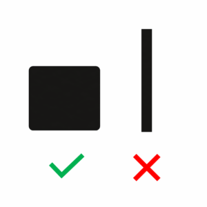
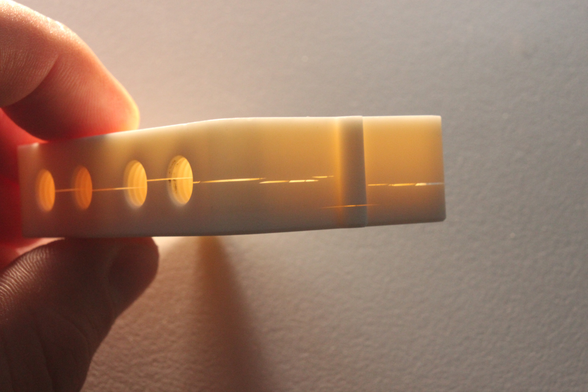
3.1 Engineering Guidelines for Ceramic 3D Printing
These values represent typical design limits for stereolithography-based 3D printing of technical ceramics. Actual feasibility may depend on part geometry and orientation. When in doubt, contact our engineering team.
Visual | Property / Requirement | Value |
---|---|---|
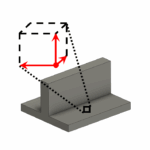
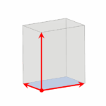
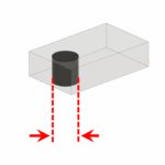
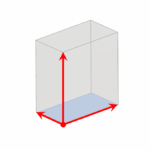
![]() | Bounding Box (max. part size) | X: 74 mm / Y: 41 mm / Z: 80 mm |
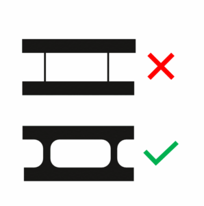
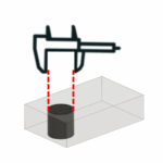
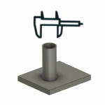
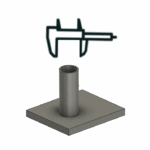
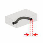
![]() | Smallest printable channel | 1 mm |
![]() | Smallest printable hole in thin wall sections | 0.1 mm |
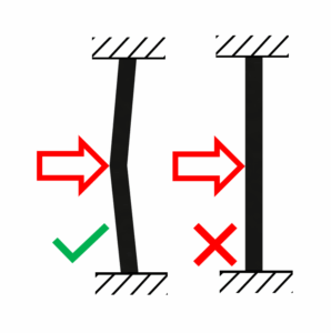
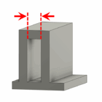
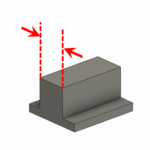
![]() | Maximum wall thickness | 10 mm |
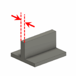
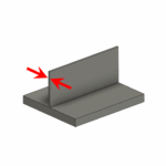
![]() | Minimum wall thickness (free) | 0.5 mm |
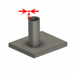
![]() | Minimum wall thickness (self-supported, e.g. cylindrical tube) | 0.3 mm |
![]() | Optimal wall thickness | 1–3 mm |
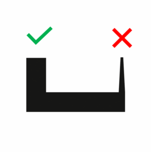
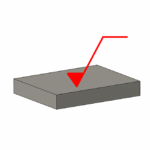
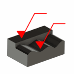
![]() | Free overhang (without support structure) | up to 2 mm |
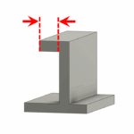
![]() | Free overhang on both sides (without support structure) | up to 3 mm |
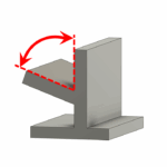
![]() | Maximum free overhang angle (without support structure) | 70° |
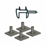
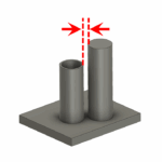
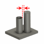
![]() | Minimum distance between features | 2 mm |
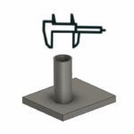
![]() | General tolerance | ±1.5 % (minimum ±0.15 mm) |
![]() | Tolerance for bores | ±0.050 mm |
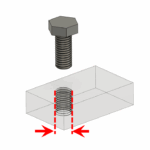
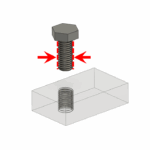
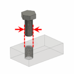
![]() | Smallest printable thread | M2 or larger, ground thread recom. |
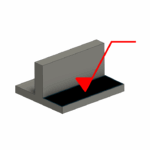
![]() | In-layer roughness | Ra 0.4 |
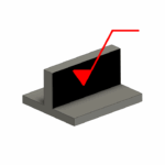
![]() | Layer-to-layer roughness | Ra 1.5 |
![]() | Voxel size after sintering | 38 µm |
3.2 Engineering Guidelines for Milling of Ceramics
The following values represent typical limits for CNC milling of isostatically pressed ceramic green bodies. Actual feasibility depends on geometry, wall thickness, and required post-processing.
Visual | Property / Requirement | Value |
---|---|---|
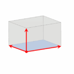
![]() | Max. part size (approx.) | X: 400 mm / Y: 500 mm / Z: 300 mm |
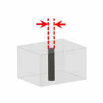
![]() | Smallest drillable hole (approx.) | 0.05 mm |
![]() | Drilled hole: Diameter/Length ratio (approx.) | 1:20 |
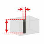
![]() | Minimum wall thickness (approx.) | 0.5 mm |
![]() | General tolerance | ±1 % (minimum ±0.1 mm) |
![]() | Smallest usable thread | M6 or larger, smaller threads must be ground |
![]() | Surface roughness (as-fired) | Ra 1.5 |
3.3 Engineering Guidelines for Grinding of Ceramics
These values represent typical in-house grinding
limits for high-precision technical ceramics. Feasibility depends on geometry, depth, material, and required tolerances. If you’re unsure, our engineering team can advise on achievable accuracy.
Visual | Property / Requirement | Value |
---|---|---|
![]() | Max. part size (approx.) | X: 200 mm / Y: 300 mm / Z: 350 mm |
![]() | Min. hole diameter (flat features, approx.) | 0.2 mm |
![]() | Minimum wall thickness | 0.1 mm |
![]() | General tolerance (prototypes, testing, small batches) | ±5 µm |
![]() | General tolerance (fully automated production) | ±10 µm |
![]() | Smallest grindable internal thread | Al₂O₃ and Si₃N₄ - M2 or larger ZrO₂ - M1 or larger |
![]() | Smallest grindable external thread | M0.5 or larger |
![]() | Surface roughness (flat & freeform) | surface finish down to Ra < 0.01 µm possible (mirror-polished) |
![]() | Minimum feature spacing (deep features) | 4 mm, smaller spacing may result in tapering due to tool deflection |
Choosing the Right Shaping Method
3D printing, milling, grinding, dry pressing, injection molding, there’s no single best method.
What matters is: What’s right for your part?
We help you find the best path based on geometry, tolerances, quantity, and surface requirements. Sometimes the answer is one process but often, it’s a smart combination.
Prototyping and Upscaling
If your ceramic part is intended for high-volume production, this is a common scenario:
A customer approaches us with a problem that needs to be solved using working prototypes. Once these are validated, he moves to a small functional batch — to make sure the chosen material and geometry actually work under real application conditions, before investing in tooling for injection molding or dry pressing.
We don’t (yet) offer injection molding or dry pressing in-house. Instead, we rely on a network of trusted partners, many of whom we’ve supported for years with prototyping and development services.
What matters is this: From day one, we keep the final production method in mind.
That means your prototype will already match — in geometry and material — what’s feasible and efficient in mass production.
Why High-Volume Production Is Not Our Focus
Large-scale ceramic manufacturing is about one thing: minimizing cost per part. That requires highly streamlined processes, a narrow part portfolio, and a company architecture optimized for throughput — not customer interaction. Our approach is different. We put engineering first. We ask questions, evaluate options, and optimize for function, not just cost.
That’s why we focus on complex geometries, low to mid volumes, and demanding specifications.
Design Affects Costs
We strongly recommend discussing your project with us before the final CAD model or assembly is finished — because design choices have a huge impact on cost. The price difference can easily be a factor of several times.
A few essentials:
- Use ceramic only where needed:
Ceramic is likely the most expensive component in your assembly. Limit it to parts where it’s truly essential. - Keep ceramics small — but not too tiny:
Parts that are too small become difficult to handle. For additive manufacturing, keep in mind that price scales roughly with the cube of the part size.
See our Online Pricing Tool for instant pricing. - Design for standard materials:
Choose cost-effective grades like our Al₂O₃ where possible. - Avoid hard post-grinding through smart design:
For example, design assemblies that don’t require precise fittings or post-machined interfaces.
As soon as you have a first draft of your part or assembly, that’s the perfect time to get in touch: